See machining deviations
Compare measured profiles and dimensions with CAD to find the areas that need review.

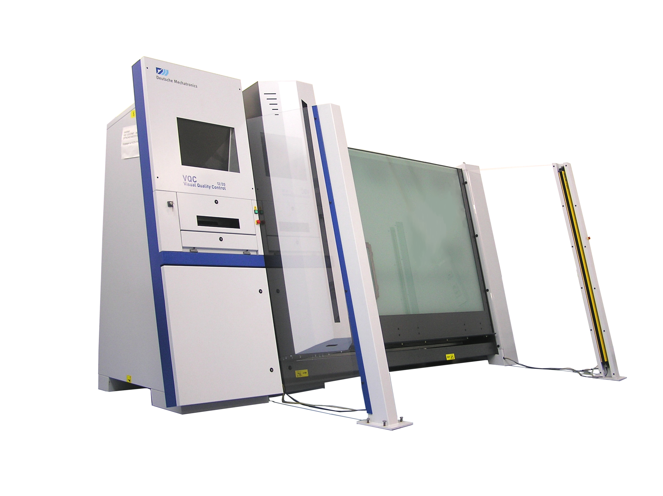
Scan flat parts and check profiles, hole diameters and positions against CAD, with records for first-part approval and delivery.
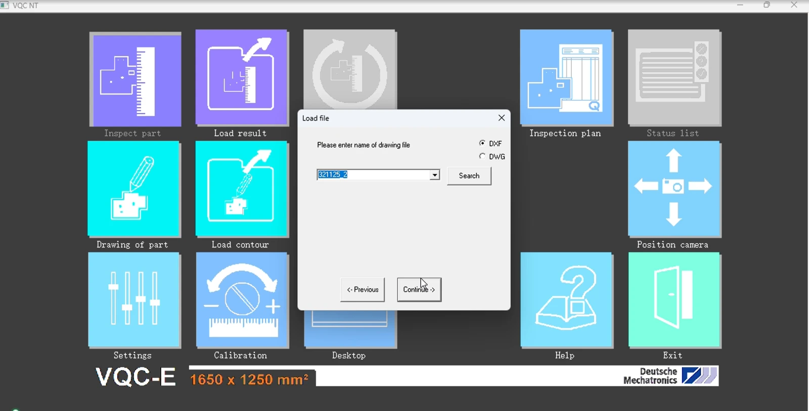
Select the matching CAD / DXF drawing or inspection plan. Nominal geometry and tolerances become the reference for the inspection.
Profiles, holes and dimensions, shown in real inspection results.
Compare the measured outline with CAD to locate deviations, extra cuts or missing cuts.
Read the result: compare the nominal value with the measured value, then check the deviation against the tolerance for that dimension.
Measure circular hole diameters against nominal dimensions and tolerances to check for oversize or undersize holes.
Read the result: compare the nominal value with the measured value, then check the deviation against the tolerance for that dimension.
Check centre-to-centre and hole-to-edge distances to identify positional deviations that may affect assembly.
Read the result: compare the nominal value with the measured value, then check the deviation against the tolerance for that dimension.
The image shows nominal angle and radius annotations from the drawing, not measured results. Confirm the required checks with your drawing and a sample.
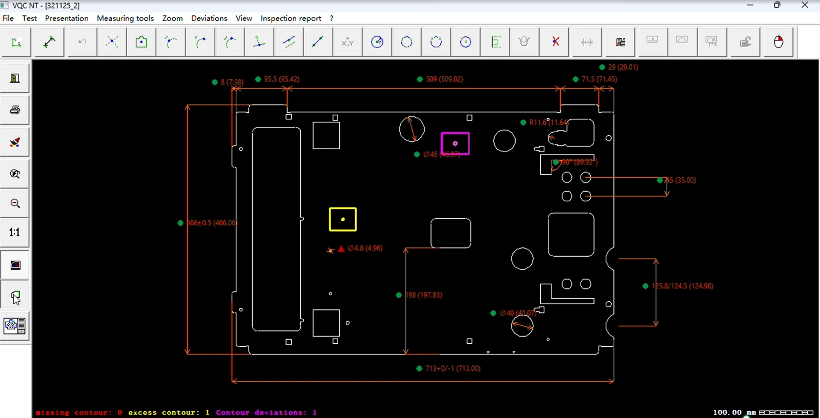
Compare measured profiles and dimensions with CAD to find the areas that need review.
See the spacing results for a sample with raised features on both sides, tested at two positions.
Review nominal values, tolerances, measured values and deviations, then create an inspection report.
Raised or warped parts: suitability depends on height, visible contours and required tolerances. Confirm with a sample inspection.
See the sample results →See how VQC and the comparison system measured the same sample at different positions.
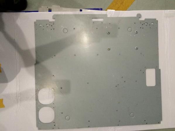
Raised features on both sides · Uneven sheet
| Part position | VQC mm | Comparison system mm |
|---|---|---|
| Centre | 623.39Within tolerance | 623.634Within tolerance |
| Left | 623.44Within tolerance | 624.282Out of tolerance |
VQC: both positions within tolerance. Comparison system: one reading outside tolerance.
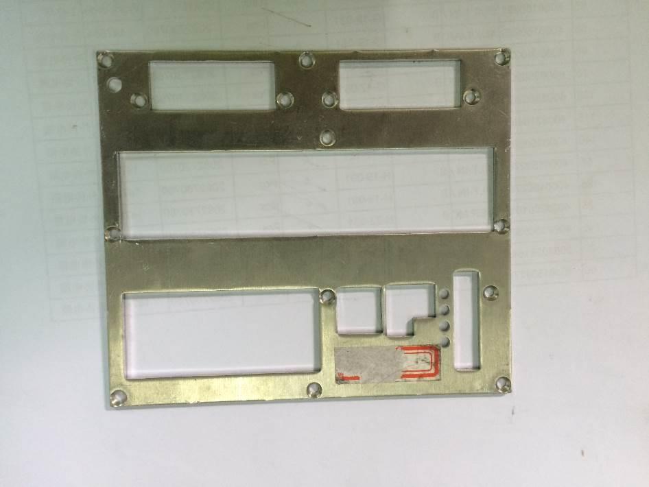
| Part position | VQC mm | Comparison system mm |
|---|---|---|
| Left | 2.88Within tolerance | 3.048Out of tolerance |
| Right | 2.88Within tolerance | 3.165Out of tolerance |
| Centre | 2.88Within tolerance | 2.930Within tolerance |
VQC: 2.88 mm at all three positions. Comparison system: two readings outside tolerance.
Historical sample tests from comparison material identified as 2016. Results and tolerance labels apply only to the dimensions and positions shown, not the whole part. Your parts can be assessed in a sample inspection.
Stable readings help your team make clearer inspection decisions.
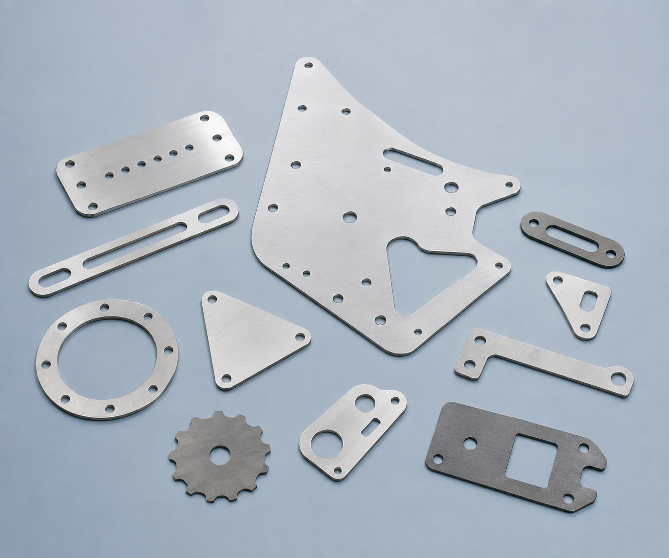 Flat sheet metal · Illustrative examples
Inspect profiles, hole positions and 2D dimensions on opaque flat parts.
Discuss your part ↗VQC checks profiles, hole positions and related dimensions on opaque flat parts. The workflow shown here does not inspect 3D surfaces, thickness or surface defects.
Compare the full loading, scanning, review and reporting cycle using representative parts, alongside your inspection volume and current process.
Bring a representative part, CAD / DXF drawing and key tolerances. Tell us which checks take the most effort.
Start with your part type and inspection challenge. With your drawing and key tolerances, we can discuss suitable checks and a sample demonstration.
Discuss your part ↗